Introduction to Hydraulic System
The genuine term hydro-static is used which means the transfer of different form of energy from pressure and flow, excluding the kinetic energy. The hydraulic system is mainly having three parts; first one is the generator that is a hydraulic pump (Smettem and et.al., 2016). Second part is the electric motor, which will drive the generator. Third part is the combustion engine, which will be used to run the machinery. All the hydraulic system's are based on the Pascal's law.
The pascal's law can be stated that, “As the system pressure is same, the force which is given by the fluid to the surroundings will be equal to the product of pressure and area (pressure * area). Therefore, a piston with small diameter will feel small force and the large piston will be facing with the large force. Most of the hydraulic system will be having the hydraulic cylinder, which will be coming in use (Lee and et.al., 2014). The same principle is used here, like very small torque is inherited into very large force. If anyone want to change the transmission ratio, then by the throttling the fluid in between the part of the generator and motor part or by the use of different motors which will be having swept volume that can be adjusted, it can be done. The major advantage of such hydraulic system is the high power density. The total mass of the hydraulic system is many times smaller than the electric drive mass, which will be producing same power.
These hydraulic drives are mainly divided into three grades;
- Mobile hydraulics
- Industrial hydraulics
- Aircraft hydraulics
This classification is done, because all the components are divided into three categories. But sometimes there can be a overlap between the mobile and industrial hydraulics. Air craft hydraulics elements are very specific and specialized (Chen and et.al., 2014). This is due to their extreme requirement of weight and accuracy. In developing the hydraulic system which is a complex one, then it is mandatory that they must have suitable and accurate advancement- methodology. This accurate methodology is used to reach the results which are necessary in short and quick time duration.
Applications of the hydraulic system are as follows;
- In car brakes- when the driver push the brake pedal, a small piston is pushes back. the pressure is applied on the brake fluid by the large piston, this pushes the brake pads, and that pad comes in contact with brake drum (Taylor, Banks and Watson, 2016). This will slow down the speed of the car and after few seconds make the car stand still.
- Air planes- To lower the barking system and adjusting the wind blades, the hydraulic system can be used.
- Heavy equipment like truck and other machinery, in unloading this system is used.
Objectives
The following objectives are covered in this report;
- To analyze different hydraulic system.
- To identify the most common steps involved in setting up the hydraulic system.
- To develop the algorithm applicable to hydraulic system.
- To analyze the desired hydraulic circuit using software.
- To develop a program for an algorithm.
Significance
The hydraulic system is the core technology backside several industrial companies. Life would not be that easy and possible without the hydraulic system. These technology is everywhere, from home to work, from stationary to mobile. If the hydraulic system is not there, the construction vehicle will not work, cable cars will not do proper functioning, trucks will not be able to unload their goods, no theater stage would rotate (Lin, Shi and Burton, 2013). The professional as well as the personal life will be very inconvenient. All the hydraulic systems are becoming more and more advanced, which is all due to the new ways of thinking and various approaches of development. Their main focus is on the hydraulic system, so that this technology will become more versatile, more efficient and become more accurate and precise.
By the use of performance electronics and various software, these hydraulic systems are becoming more and more intelligent and advanced. The development of such new technologies and the use of advanced software, all these complex systems are transforming and changing, so that it will be very easy to use (Yao, Jiao and Ma, 2014). There will be further improvement in the technology. The high performance sensors will be very helpful in the self-monitoring of the systems. The maintenance will not be on the frequent basis because the equipment's are very long lasting and the maintenance will be dynamically. The hydraulic system will have some benefits and advantages which will make it more efficient in power transmission, they are;
- The system can be controlled with very ease. The accuracy is also high. This can be done just by the use of simple levers and some push buttons.
- The system can be very easily starts, stop, slow down and speed up.
- The force multiplication can be done, the power system driven by fluid can multiply the forces very simply and in more efficient way from a portion of pound to various tons of output.
- The force and torque is constant- only hydraulic system is capable enough to provide the force and torque in constant way. This is regardless of the changes in the speed.
- The hydraulic system is very simple, more safe and economical. The moving parts are very few in relation with other mechanical and electrical transmission system. Therefore, the maintenance is very easy and simple.
Despite having all the highly desirable features, this system is having some negative impacts as well. They are;
- The hydraulic oil handling is very messy job (Ko and et.al., 2015). The leakage will always be there, and it is close to negligible to eliminate the leakage from the system.
- The hydraulic lines will always be having high pressure. So these lines can burst at any point of time, which can cause the injury to human.
- The hydraulic oil which is leaking is having a tendency of catching the fire. This risk will be more when the system is working in hot regions.
Report organization
This report consists of 5 different chapters, which will cover up the entire development of the entire algorithm process and its use in hydraulic systems.
- Chapter 1 will provide the information of hydraulics, the hydraulic fluid which is commonly used and the several hydraulic systems which are used in day to day life.
- Chapter 2 is consisting of the development of the hydraulics system and the processes by which the system is being made. This will include different procedures and types of different hydraulic system.
- Chapter 3 will describe the algorithm and how it is developed. There are certain steps, which are involved in the make-up of algorithm, so this has been discussed in this chapter.
- Chapter 4 presents the planning and the uses of this algorithm. How the algorithm is planned and implemented in the systems?
- Chapter 5 will be the final part and it is the conclusion. In this whole report what are the outcomes, and the impacts and some recommendations regarding the hydraulic system will be covered in this chapter.
Chapter 1
Hydraulics system is a function of mechanical engineering, which uses the force of liquid pressure to operate. In such type of systems, the movement of the components is produced with the help of contained liquid, which will be passing through the cylinders moving piston. The hydraulic system is the combination of mechanical, electronics and the software engineering, also known as mechatronics. This is used in designing and manufacturing of various parts or products. Some basic hydraulic system uses only water as a fluid medium. They uses the force of gravity to create the pressure of water (Wang, T. and Wang, Q., 2014). Some of the more complex systems uses the pumps in which the piston is moving inside a cylinder, so that the oil gets pressurized. The valves are there, to control the flow of liquid.
These hydraulic systems are very much similar to the pneumatic systems. Both these uses the fluids, but pneumatic uses gases and hydraulic uses fluids. The hydraulic system is capable enough to generate the pressure up to 10000 pounds per square inch, and the pneumatic can only generate about 100 psi. Some of the components of such hydraulic system are as follows;
Hydraulic pump: The pump uses the form of mechanical energy and converts it into hydraulic energy. The change in the form of energy is done by the movement of fluid, which is used as the medium of transmission. The hydraulic pumps may have gear pump, vane pump and also the piston. All such kind of pumps will have their specific application like variable displacement pump, bent-axis piston pump etc. The main function of all these pumps are same, which is the displacement of the fluid against friction and pressure.
Valves: Hydraulic valves are used to start or stop the system. These can also be used to direct the flow of fluid. These valves are having spools and poppets. All these can be actuated by the means of pneumatically, electrically, hydraulically or mechanically.
Cylinder: The hydraulic cylinder are basically the actuators. They are the end result of the Pascal law. In such actuators, the hydraulic energy gets converted to again in mechanical energy. This is done by the help of hydraulic cylinders. In such cylinders, the hydraulic energy is converted into the linear motion and work. For this purpose, the hydraulic motors can also be used.
All these hydraulic systems are using the hydraulic fluids. The main function of all these fluids is to give smooth operation and easy energy transmission (Ben-Galim and et.al., 2016). These fluids are used for the lubrication purpose, the control of contamination and for the transfer of heat. Some of the frequently used hydraulic fluids are;
- The mineral based fuel or the petroleum based fuels. These are the most used hydraulic fluids. The quality and the performance of such kind of fuel is totally dependent on the process of refinery or the additives which are being used. The additives will have certain properties like, the rust and oxidant inhibitors, anti corrosion agents. These fluids are low on cost and the quality is also high and is always available.
- The second one are based on water. These are used to contain the fire because they are having high water content. These are available in water oil emulsion or oil water emulsions, some times in water glycol bends.
- Synthetic fluids are made by man, and these fluids are having excellent characteristics of lubrication even in high temperature and high pressure systems. The main advantages of such fluids are; more fire resistance property, high thermal stability and reduction of friction. But these fluids are more expensive than the other two fluids. These fluids sometimes mat be a little toxic in nature so they require special arrangements of disposal.
Chapter 2
The hydraulic systems uses the power of fluid under very high pressure to lift the load. So on the basis of this, there are three main types of hydraulic systems;
Open center support: The fluid will keep on flowing in the whole system, unless the actuator remain idle. The idle system means that no pressure is applied. The fluid will flow from the reservoir, through the pump and the valves and again back to the reservoir. The valve position is the main thing to build up the pressure in the system (Casoli and et.al., 2015). The valves remain in neutral position, if the actuator is idle. The actuator is changing its position, means if it is up, all the valves are out of their neutral position. The pump will start to bear the load. The volume remains constant and there is no pressure regulator in open system.
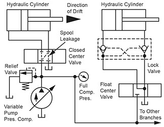
Closed center support: in such system, the fluid is always under certain pressure. The pump is operating and releasing and when a certain value is reached by the pressure regulator. The selector all are always in parallel system, not in series like in the open system.
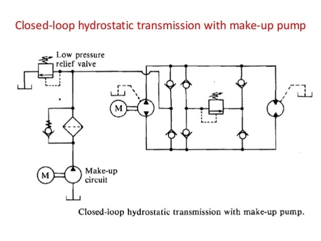
Combination support system: This system is having the functions of open as well as the closed center system. In such systems, the hydraulic capacity is served by closed system and the auxiliary applications are handled by open system. The performance will always remain high, even in the cold conditions. This system is having more number of parts, means the requirement of different subsystems.
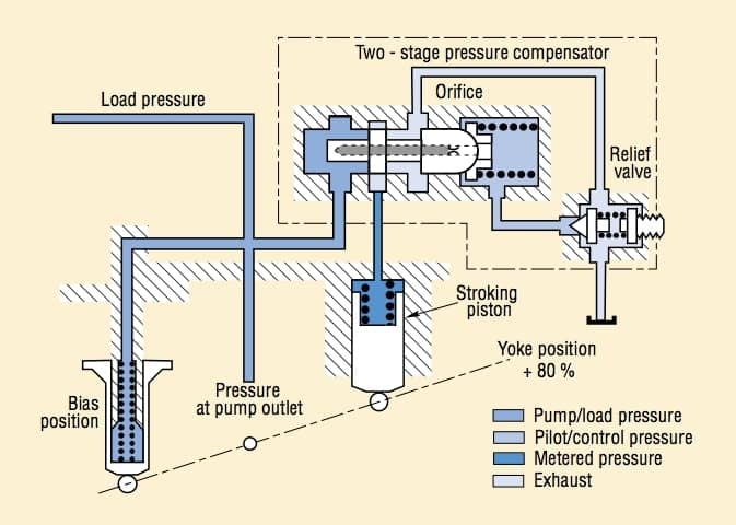
The hydraulic systems are having some advantages like;
- The fluid used by the system is in-compressible which will give the higher efficiency.
- The power output delivered by this system is consistent, but this will be difficult for the pneumatic or mechanical systems
- the possibility of leakage through these systems is very less, because of the high density in-compressible fluid.
- The cost of maintenance is very low.
- The performance in hot climate condition is also very high.
But such system are having some disadvantages as well;
- The material of all the component like tank, pipes, piston can get corroded because of the hydraulic fluids. So the person have to be very careful while selecting the material.
- The size and weight of the system is very high, so it is not suitable for the small equipment.
- Very small impurity can damage the whole system permanently, so the size of micron filter should be very careful.
- The leakage can cause fire, so use of proper seals is required.
- Such fluid is hard to dispose, and this can be very harmful to the environment.
If anyone is having any kind of hydraulic system, then it is mandatory to understand the use of hydraulic pumps (Editors of Hydraulics & Pneumatics, 2012). There are different types of hydraulic pumps;
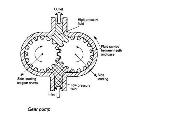
Gear pump: Different machines and all the combustion engines needed the correct amount of the lube oil, so that they can run very smoothly. Different machines are having thousands of gears which need to be lubricated and the gear pump does exactly the same (Mahdi, 2017). These pumps are now used as the system of lubrication, which supplies the gear with the required amount of lubricants. These pumps makes sure that the lubricant reaches to all the components. The hydraulic steering system is using gear pumps to move the fluid.
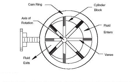
Vane pumps: These pumps are used in the die-casting or different molding machinery. The flow pulsation is comparatively low in these pumps. The flow is always constant in these pumps, so the noise produced is also low, even if the speed of the machine is high. The operating pressure of these pumps will not cross over 175 bars. But some of the vane pumps are designed in such a way that they can operate on 300 bars also. These pumps are important in the construction of land and road machinery.
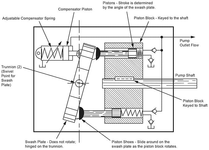
Axial and radial piston pumps: The axial pumps will operate in both open and closed circuits. Thus, it will be having variable setting of speed or it can be fixed. The change in the direction of fluid can be done and the operation is also very simple (Vaezi and Izadian, 2015). But if the system is containing high pressure which is around 400-700 bars, then radial piston pumps are very useful. The piston inside the pump will extend in the radial direction and this will be around the drive shaft. These pumps are generally very efficient and produce very less noise.
The hydraulic systems are generally used in industrial plant and the environment. And apart from this, the marine industry is highly using the hydraulic system (Reed and Löfstrand, 2015). There are hundreds of applications are there which are having such systems, and some of them are;
- The machine tools which are used for metal cutting
- Different conveyor systems
- Some primary metal plants and foundries
- For packaging of different products
- In ship's steering system
- Paper industries, in press printing machines
- In grinding and honing applications
- In robotic and material handling system.
The algorithm or the analysis is very essential in the designing of the hydraulic system and the transmission of various machinery; like machine cutting tools; self propelled chassis etc. This is done ti simulate long before the beginning of production model and its related working processes, so that we came to know about the weak places in the hydraulic system. This mathematical system will be consisting of different technical system which are also of different class like electric, electric, hydraulic etc.
For the build up of this dynamic model of the hydraulic system, the latest and most advanced method of finite element-node structure is used. This whole new system will be divided conditionally and according to that all the components are divided in the form of input and output. To design any hydraulic system, the major component of the system can be: hydraulic motors, pumps, hydraulic cylinders, different valves, load resistance which is the throttle, pipelines, the pneumatic or spring accumulator, pilot operated check valve, power regulator, wheel carrier and directional control valve. After knowing all the elements and components used in the hydraulic system, the simulation is done, but there are certain things which are necessary while doing this dynamic process. They are;
The algorithm of the hydraulic circuits, the hydraulic elements and their base, arranging the data and the preparation of algorithm, automatic system, which will describe the solving process of algorithm, the methods which will be used in solving those problems, the dynamic calculation of any hydraulic circuit and lastly the way of presentation. The analysis of various hydraulic system, which are applied in various hydraulic machines clearly shows that, the set of hydraulic machine is very finite and some very essential elements are there by the means of which, to analyze the circuit of any hydraulic drive is possible. The calculation and making of algorithm is decided by the application of variable pressure, the speed, different flows and position of parts, which are placed in the hydraulic circuit. These node can be used in one another, like one same node can be an output of one element and the input to another element.
Any hydraulic circuit will have some predefined set of elements which will be helpful in making the circuit and the nodes which are the point of connections of each elements. Each hydraulic circuit can be presented in three nodes, except directional control valve. The nodes will be I (input), J (output), K (transformation of energy control).
References
- Ben-Galim, Y., & et.al., (2016). Modeling of an Experimental Hydraulic System With Two Flow Control Parameters. In ASME 2016 International Mechanical Engineering Congress and Exposition (pp. V011T15A013-V011T15A013). American Society of Mechanical Engineers.
- Casoli, P., & et.al., (2015). Coupling excavator hydraulic system and internal combustion engine models for the real-time simulation. Control Engineering Practice. 41. pp.26-37.
- Chen, Z., & et.al., (2014). Improved gravitational search algorithm for parameter identification of water turbine regulation system. Energy Conversion and Management. 78. pp.306-315.
- Ko, J., & et.al., (2015). Development of brake system and regenerative braking cooperative control algorithm for automatic-transmission-based hybrid electric vehicles. IEEE Transactions on Vehicular Technology. 64(2). pp.431-440.
- Lee, J., & et.al., (2014). Prognostics and health management design for rotary machinery systems—Reviews, methodology and applications. Mechanical systems and signal processing. 42(1). pp.314-334.
- Lin, Y., Shi, Y. & Burton, R., (2013). Modeling and robust discrete-time sliding-mode control design for a fluReed, S. and Löfstrand, M., 2015id power electrohydraulic actuator (EHA) system. IEEE/ASME Transactions on Mechatronics. 18(1). pp.1-10.
- Mahdi, S.M., (2017). Investigation and Enhancement Using Different Types of Pipelines for the Servo Hydraulic System with PID Controller Tuned Using Fuzzy Logic. Al-Nahrain Journal for Engineering Sciences. 20(1). pp.158-166.


